Nerpen Drawings of homemade aerosas "Otter
Drawings of homemade aerosas "Otter"
(Think first)
Aerial drawings. For open snow-covered expanses, in my opinion, there is no better vehicle than Aerosani. No other all-terrain vehicle compares with them at speed and passability. Noise, though, a lot. But but, what a pleasure from rapid slip on untouched snowy virgin! Aerosani, called "Example" including for, let's say, the prurdity - at the speed of them, you can even through a rare shrub "Skinny", - I built in one breath: I wanted such a car for a long time. And so the design thought it thoroughly, and the necessary aggregates, nodes and materials prepared in advance.
Aerosani constructively consists of a boat ski with an open single cabin in the central part. The cab is extremely simple: it only has a driver's seat, controls and a luggage regiment. From the driver's incident air flow protects the fairing with windshield. For the cabin, on the stern of the sled, the engine frame is installed, to which the gasoline engine of air cooling with a capacity of 18 hp is suspended. with an air screw with a diameter of 1200 mm. In the same place, on the stern, there are two aerodynamic keel on sides, simultaneously serving the root of the zone of the rotation of the air screw.
The aerosan hull is a boat of variable cycleness. All its power elements are 11 spangling, longitudinal stringers, bims and trim - made of wood.
Instead of a keel, the boat across the entire length has a ski, which is narrowed to reduce resistance from the nose to the transnt from 300 to 270 mm. Its sock is curved by a radius of 1000 mm. Beyond the bottom of the bottom of the skiing protrudes on 50 mm, and from the channel number 7 to the transnta smoothly rises by 20 mm. In the diameter, the sole of the ski and the bottom of the aerosans slightly convex. The cilancement of the case on the transom 11 ° with a gradual increase of up to 24 ° on the face. The splint sets are made of BS plywood 10 mm thick. All of them, except for the transom, are facilitated by cutouts. Spanmost No. 3 and 8 serve as partitions separating the cabin from the nasal and feed compartments.
The width of the cockpit is chosen such that its boards tightly fixed the driver in the chair. The soles of his feet rest in the Spand No. 4, which gives additional convenience in the management of anesthesia. In all skiing skis from the spline number 1 to the transnt, blocks of 50 mm thick of PS-1 foam was pasted. On top of the blocks from the Spand number 3 to No. 8, the floor of 3-mm plywood was pasted. The same material is trimmed and boarding the cab.
Moreover, on the left and right, part of the sides of the sides are made in the form of removable panels for maintenance of control knots. The deck and the bottom are trimmed with a plywood thickness of 3 mm, sole ski - plywood brand BS 5 mm thick. Racks of the spangling number 5 are reinforced with pine plates in the location of the sleeves under the trees of control levers. The lower parts of the side branches of this spline are separated from the racks, shortened so as not to interfere with the movement of the steering bumps, and are reinforced with bubbles glued to bottom stringers. In the corner of the case, reinforced stringers are placed serving for the installation of a motor frame and rocking faces, control, as well as bims (they are glued to onboard private bars) for fastening aerodynamic keel, wedge-skates and steering wheel.
Deck and bottom stringers in the places of intersection with the splits are additionally fastened with wire loops. Wedge-skates are made of 16 mm plywood brand BS and are located strictly parallel to the longitudinal axis of the aircraft housing. In bims, they are glued with spikes. Wedge-skates are reinforced by bobbers who make their transition to the housing, and stainless steel edging (installed after the complete availability of the case). The surface of a fully assembled and trimmed plywood housing is covered with putty, aligned and carefully cleaned. It is then saved by one layer of fiberglass brand AST (b).
Ski is brought by a sheet of stainless steel with a thickness of 0.5 mm, and the bottom - a sheet of low pressure polyethylene. On the sides of the ski attached with the screws with the secret heads two subsidements made of steel brand U10a. I picked up the exact position of the sub-sized by experimentally by rearring them to the nose or stern of the aircraft hull (for this in the figure there are several mortgage nuts). For the sole of the skiing down, cuttings protrude 12 mm, however, like feathers of the wheels of the direction. This achieves excellent aircraft handling on ice, Nastya and Radan Snow Road.
The fairing is frozen from the aluminum sheet with a thickness of 1.5 mm. He does not have the power spangling. The rear edges of the shell and the lid of the luggage compartment are strengthened in them with a wire of the ABS stamme with a diameter of 2 mm. The fairing casing is attached with round heads through the frame from the bars with a cross section of 20x20 mm, pre-mounted on the deck over the trim. The volume under the fairing is used for small cargo and a medical aid kit.
Wind visor - from organic glass 4 mm thick. The method of giving the glass of the desired form is clear from the attached pattern. The visor is attached to the beacon with bolts M4 together with the lid of the luggage compartment. The finished body with a fairing for safety purposes is covered with bright nitroglyphthal paints of yellow and red colors. The driver's seat is easy, opens access to the instrument box located behind the back. An arranged chair from PS-1 foam and fiberglass AST (b) on Epoxy resin ED-5. From above is the leather-proof. Fixed by the protrusions of the Spedding number 7, which are in the deepening of the seat.
Aerodynamic keels are installed on sides of the corps of the case. Each keel has a framework, consists of anterior and rear edges, ending, three ribs and a spar. For greater strength, the internal cavities of the frame filled with foam blocks of PS-1, and the frame itself is trimmed with a plywood thickness of 3 mm and painted: on a yellow background - red stripes. Attached by two bolts M6 to Bimsu (bottom) and one M6 - to a troop (from above). In the trim keelle above the root ribs are made of cutouts: under the front bolts of fastening (on the inner surface) and under the tower steering wheel (through). In these places, it is removed, of course, the filler is a foam.
The air screw is pushing, glued (from birch regions). Made according to the drawings published in the magazine "Model-Designer" No. 1 for 1975, with a slight change in the step towards the increase. Screw painted in red. At the ends of its blades of black paint depicted edging and parallel to her strip.
STEERING. The aerosan course management system consists of two parallel, symmetrical and independent one from another branches - right and left. Each branch has the same set of elements: lever with rubber handle, shaft, two bumps, two thrust, rocking chair and steering feather. Levers - from steel pipe with a diameter of 22x2 mm. From the most rubber handles, they are slightly flattened for greater rigidity. Clamps with split sliced \u200b\u200bholes are welded to their ends, filmed on the steering shaft bolts.
Steering shafts rotate in steel sleeves glued, as already mentioned, in the struts of the page number 5 and stuffed before assembling Li-Tol-24 lubricant. On the other side of the levers on the shafts, steering bumps are installed (connecting rods from the carriage of the children's bike "Eagleok") and are made by bicycle wedges. The ends of the bustle are articulated with forks of long steering, with the help of steel coiled and pinned fingers. Other ends of the thrust are hinged with the inner shoulders of the rocking hours rotating on closed and not requiring lubrication of the bearings 60201.
The stripping axes rocking faces are rigid on the amplification of deck stringers. On the axes of the rocking chair are fixed with crown nuts with linings. The outer shoulders of the rocking chair are hingedly associated with short traction that are attached to the bumps. The lower ends of the shafts of the steering wheel are included in the heels of edging of wedge-skates. Steering feathers from steel brands U10a, reinforced on two sides, strips of the same steel are welded to the shafts of the steering wheel. Trees of steering wheel rotate in steel sleeves pasted into bims. In addition, the bushings have brackets with the help of which they are additionally attracted to the aircraft casing by the rear bolts of fastening aerodynamic keel.
All parts of the steering mechanisms, except for the thrust and bustle, are made of steel 45 followed by hardening. Trees of steering wheel (after partial disassembly) are covered with lithol-24 lubrication. Feathers of steels have an angle of maximum rotation of ± 35 ° from neutral position. In addition to lubrication, no other periodic interventions and adjustments, steering aerosan keys does not require. For what purpose are two parallel, symmetrical and independent branches of the control system? First, I wanted to have effective brakes.
Taking both levers on itself, the feathers of the steering wheel can be turned inside, towards the ski, thereby creating a plow effect - braking will occur. (The same result can be achieved when pressed levers from ourselves, with the only difference that the feathers turn outwards. Long steering thrust in this case will work on compression and due to its thin walls can be deformed. Therefore, such a position of levers when braking undesirable.)
Secondly, when the aerosanis turns on a snowy virgin, the housing is incremented towards turning, and the pen steering wheel, opposite to turn, is partly, and in some cases it completely comes out of the engagement with the snow cover. Therefore, it is done so that it worked exactly that the steering wheel, the pen is in the snow cover, and the long steering traction was tensile. Thirdly, the shoulders of the bumps and the rocking boards are the same, and the gear ratio to the control lever is approximately 1: 3.2, so the driver's hand responds to overload on the steering wheel and there is an opportunity to parry its control lever, not allowing breakdowns. Fourth, when moving in direct or by a large radius curve, you can use any of the levers. The free lever itself is automatically tracking the direction of movement.
The fuel tank is a transparent plastic canister with a capacity of 5 liters. Installed behind the Spanmost number 8 in a special container made of aluminum sheet with a thickness of 1 mm and embedded into the deck. From above, the tank is fixed with a rubber belt with steel hooks at the ends, which he keeps behind the container brackets. The intake tube made of oil-resistant rubber comes out of the canister through the plug and stretches to the manual pumping pump, and from it to the mechanical diaphragm engine pump.
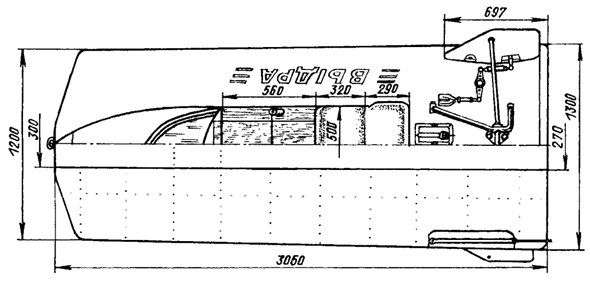
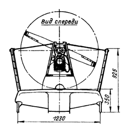
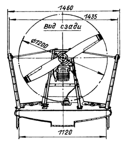
Aerosani "Otter" (on top of top The engine is not conditionally shown)
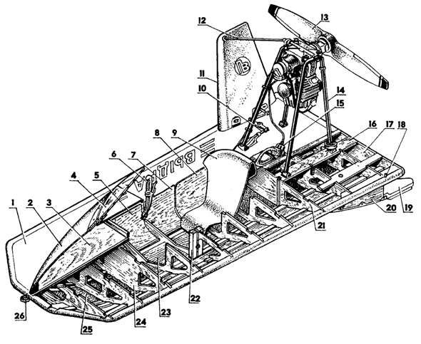
Aerial layout: 1 - housing; 2 - fairing; 3 - luggage shelf; 4 - wind visor; 5.8 - non-removable right cabbage panels; 6 - the right handle of the course control (with the "Gas" lever and the "Stop" button); 7 - removable right cabin panel; 9 - driver's seat; 10 - Right Course Management Movement; 11 - right kil; 12 - right subproof; 13 - air screw (diameter 1200); 14 - motor frame; 15 - fuel tank; 16 - Left Stringer under the motor frame; 17 - Traven; 18 - left axis of the steering wheel; 19 - left pen steering; 20 - left wedge-horse; 21,24 - Spanmost partitions; 22 - lining of the left lever lever. 23 - floor cabin; 25 - foam filler; 26 - Ry
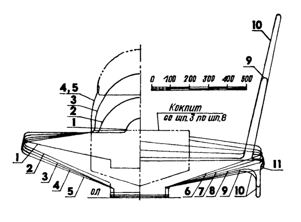
Theoretical drawing of Schandamov
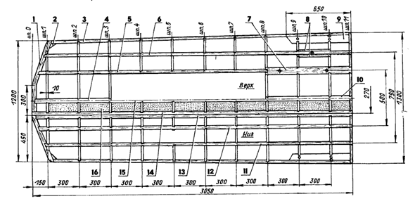
Main power set of aerosan hull: 1 - nasal trigger bar (pine, bar 50x30); 2,20- books (pine, 6 pcs.); 3 - side fitness timber (pine, bar 50x30, 2 pcs.); 4-nasal carlangs (pine, rail 50x 15); 5.6 - Deck Stringers (Pine, Rake 30x10.4 pcs.); 7 - Stringer under the motor frame (pine, bar 70x20,2 pcs.); 8- strengthening of Stringer (pine, rail 20x10, 4 pcs.); 9-BIM KILA mounting (pine, bar 80x70, 2 pcs.); 10 - Feed Karlents (Pine, Rake 30x10); 11-13 - Badge Stringers (pine, rail 30x10, 6 pcs.); 14 - Stringer Ski (Pine, Rake 50x50, 2 pcs.); 15 - Kiel (Pine, Rake 50x 15); 16 - liner (foam, 10 pcs.); 17 - Rack of the Spanmost number 5 (Plywood BS, S10, 11 pcs.); 18 - sleeve under the exchange handle shaft (steel 45, pipe 16x2, l40, 2 pcs.); 19 - Course control lever rack (pine, rail 30x30, 4 pcs.); 21 - washer (steel 45, 036x16x2, 2 pcs.); 22 - Tramen (Plywood BS, S10); 23,25 - Basins (pine, 4 pcs.); 24 - Wedge-horse (plywood BS, S16, 2 pcs.)
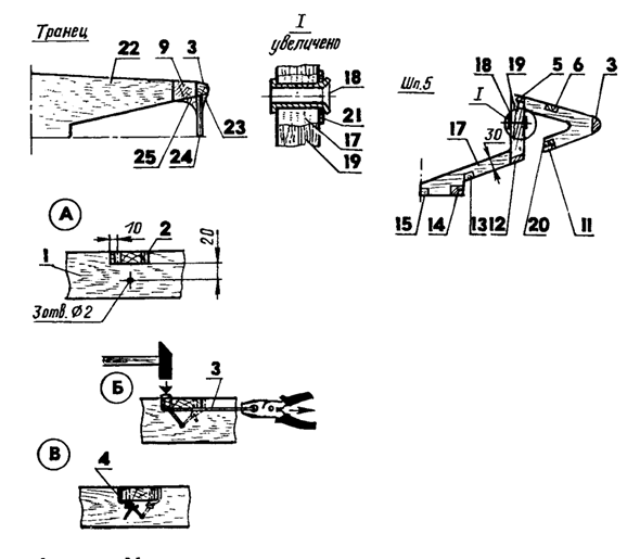
Additional fastening of stringers: A - drilling holes in Stringer and Spanort; B - the formation of the first twist and the tension of the wire; B - the formation of a second twist; 1 - spline; 2 - Stringer; 3 - WAT wire with a diameter of 1.2; 4 - Ready mounting knot
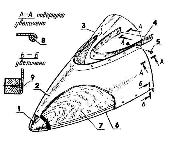
Nasal Aero Schedule: 1 - Basin (Pine); 2 - the shell of the fairing (aluminum, sheet S1,5); 3 - wind visor (organic glass, S4 sheet); 4 - the roof of the luggage compartment (aluminum, sheet S1,5); 5 - bolt M4 (9 pcs.); 6 - frame (pine, rail 20x20); 7 - luggage shelf (plywood S3); 8 - flaming (wire of ABS diameter 2); 9 - Shock 6x16
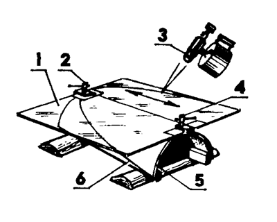
A method of manufacturing a wind visor: 1 - Visor's workpiece (leaf of organic glass); 2.4 - clamps; 3 - soldering lamp; 5 - model (pine, plywood); 6 - Prothesing line
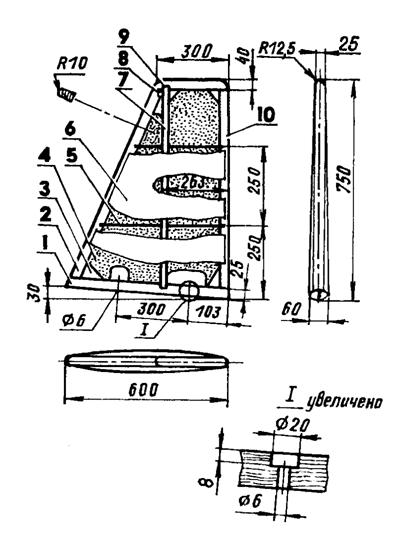
Keel aerosanis; 1 Castle rib (BS, S20 plywood); 2-front edge (pine, rail 40x25); 3 - Basin (Pine, 5 pcs.); 4 - filler (PS-1 foam); 5 - rib (plywood S3, 2 pcs.); 6 - covering (plywood S3); 7 - spar (pine, rail 25x25); 8 - opening 06 for the bolt of fastening of the pan; 9 - ending (pine, rail 40x25); 10 - rear edge (pine, rail 40x25)
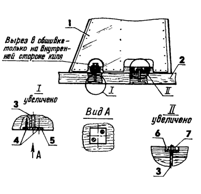
Kiel mount: I - Kiel; 2 - BearS; 3 - bolt M6 (2 pcs.); 4 - screws 3x20 (4 pcs.); 5 - weld head bolt (steel 45, leaf 30x30, S2,2 pcs.); 6 - 20x6x2 washer (2 pcs.); 7 - Nut M6 (2 pcs.)
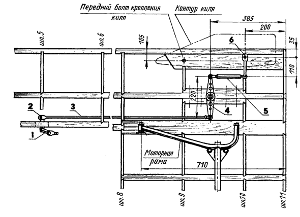
The main elements of control posting (right branch): 1 control; 2.6 - steering bumps; 3 - long traction; 4 - rocking chair; 5 - short thrust
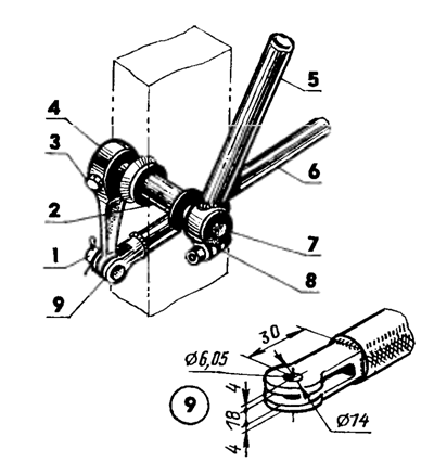
Construction of the right lever control unit: 1 - finger diameter 6 (steel 45); 2 - sleeve under the lever shaft (steel 45, pipe 16x2, L40); 3 - Wedge (from the Bicycle Kit "Eagleok"); 4- steering thai (connecting rod from the bicycle cart "eagle"); 5 - control lever (steel pipe 22x2); 6- steering thrust (steel pipe 16x1,5, L13 25); 7 - shaft (steel 45, rod with diameter 12); 8 - lever clamp (steel 45); 9 - tip steering thrust (steel 45)
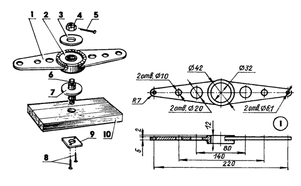
The design of the Rocking Molding Node: 1 - Rocking (steel 45); 2 - Bearing 60201; 3.7 - 20x12x2 washers; 4 - crown nut M8; 5 - plinth; 6 - axis-pin M8 (rod with diameter 12); 8 - screws 3x6; 9 - mortgage Nut M8; 10 - Deck Stressed Stringer
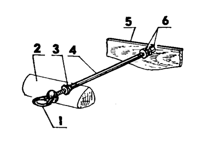
Installation of fish: 1 - rhy-nut M6; 2 - nasal boll; 3.6 - controlling MB; 4 - hairpin M6; 5 - Spand number 1
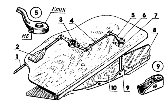
Drive steering wheel (left branch): 1 - Long steering (steel pipe 16x1,5, L1325); 2 - the boot (tarpaulin, slides freely); 3 - Rocking; 4 - short steering (steel pipe 16x1,5, L185); 5 - tower steering; 6 - shaft steering wheel; 7 - shaft sleeve; 8 feather steering; 9 - heel (stainless steel); 10 - Wedge-Konk
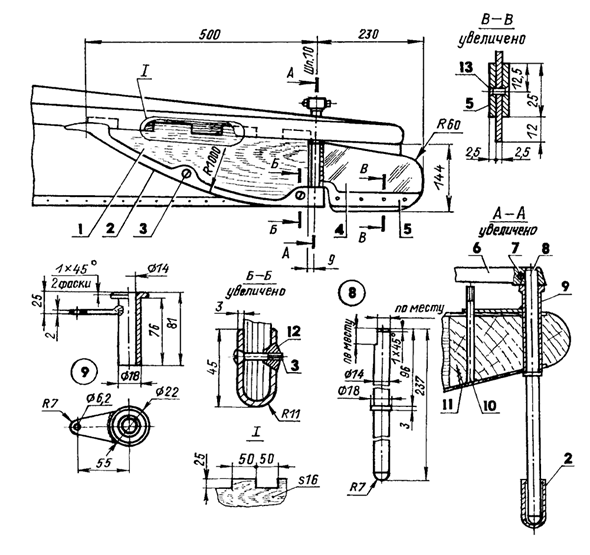
Design of wedge-riding and wheel drive direction: 1 - wedge-horse (plywood BS S16); 2 - edging (stainless steel, strip S3); 3 - bolt M6 fastening edging (3 pcs.); 4 - pen steering (steel U10A, sheet S2.5); 5 - Feather lining (steel U10A S2.5); 6 - Cup of the steering wheel (from the bicycle carriage "Orlenok"); 7 - Wedge (from the Bicycle Bicycle Bicycle); 8 - shaft sleeve (steel 45); 9 - shaft steering wheel (steel 45); 10 - rear bolt M6 kil fastening; 11 screw screw bolt head (2 pcs.); 12 -Kladnaya nut M6 (2 pcs.); 13 - rivet (diameter 3, 4 pcs.)
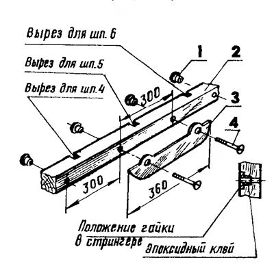
Installation of the left underground: 1 - figure nut M8X1.5 (4 pcs.); 2 - Stringer Ski; 3 - subsidence (steel U10a, S2); 4 - Boltm8x1.5 (2 pcs.)
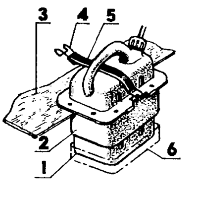
Installation of the fuel tank: 1 - fuel tank (plastic canister with a capacity of 5 liters); 2 - container (aluminum, sheet S1); 3 - deck; 4 - hook (steel wire with a diameter of 3, 2 pcs.); 5 - clamp (rubber belt); 6 - pallet (aluminum, sheet S 1)
Drawings of homemade aerosas "Otter"
(Part two)
An aerosan engine frame is a welded structure made mainly of steel pipe 22x2. The main power elements of the frame - arcs are bent in the heated state of the pipe segments pre-stocked down by sand. The ends of the arcs have horizontal clip under the mounting brackets to the anesthesia housing, and the middle (above) are connected by the crossbar to which the four vertical engine suspension robes are reinforced with steel brazers with a thickness of 2 mm.
In the same time, on the left and right, the welding arcs are attached to the welding arcs from the pipe 16x2 under the plugs of the windows of aerodynamic keel. To the rear end of the left arc, before welding the bottom of the climb, there are two details: a ring of steel wire with a diameter of 6 mm and a starting pulley. The first grabbed welding and is intended to limit the course up of the second, and the second, freely moving on the arc, is to start the engine with a cord. The ring for easy sliding pulley is periodically covered with lithol-24 lubrication.
Using the pulley, the engine is started as follows. The driver hills the launch cord on the flywheel (one and a half or two turns), raises the pulley to the ring, puts the cord on it and smoothly, but with force pulls him on himself. The engine begins to work, the cord jumps from the pulley and that under the action of gravity falls down the arc down, occupying its transport position. The engine (cylinder down) is attached to the motor frame by four M8X1.5 bolts through shock absorbers - rubber bushings inserted into vertical clips.
Bolt nuts are chatted. Similarly, the aerosano housing, or rather, the engine frame itself is attached to the brackets on reinforced stringers. In the same way - through the rubber shock absorbers, only with steel plug-in fingers with a diameter of 6 mm instead of bolts, are attached to the engine frame of the aerodynamic keel.
Outer Aerial Engine - gasoline, single-cylinder, two-stroke power 18 hp And the most important thing is homemade, made of nodes and parts of various boat, motorcycle and starting engines.
Motor Carter Molds from an aluminum alloy AP2 under the landing sizes of the crankshaft from the PD-10M start-up engine and has a connector with a similar "Puskachovsky" Carter, a connector with four bolts M8X1.5 (in two seating holes for them, steel control bushings that task the accuracy of the Carter assembly were introduced for them) and two screws M6 (below).
The settlement flow of the seating surfaces of the crankcase parts was carried out on the lathe with the use of simplest devices. Purpose channels and all internal surfaces are thoroughly processed manually. Carter's tightness provide gaskets and rubber reinforced cuffs.
The crankshaft, as already mentioned, from the "start". For installation, the Magneto Drive HamphTe \u200b\u200bMagneto Front Shank is refined: first, a bit shorten; Secondly, the groove was chosen in his neck under segment key; Thirdly, the axial hole with the M6 \u200b\u200bthread is drilled for the fastening screw of the demummouft. In the crankshaft crank cart rotates in three bearings: its front shank will put one bearing - roller 2206, on the rear two - roller 2206 and ball 206
Lubrication channels of all bearings are expanded. In addition, there are three spacers for shanks with a thickness of 1 mm: one on the front and two - to the rear.
Flywheel, too, from PD-10m. On the perimeter of his rear end, six M8X1.5 thread holes are drilled for the hub mounting screws. To the last four bolts M8X1.5 docked the air screw. The heads of the screws and nuts of the hub bolts are completed in a circle with steel wire.
The cylinder together with the sleeve - from the engine of the Motorcycle "Izh-Planet-3", will be pulled to the Carter with four pillars M10. In the right side of the cylinder (in the cover of the bypass channel), three holes are drilled: two threaded M5 for fastening the diaphragm pump and one for the filling of the rubber hose, which is connected to the fuel pump. Piston with rings and piston finger too from PD-10m. Only in the piston skirt are cut additional windows with a size of 30x30 mm.
Magneto drive alummoupes are sharpened on a lathe from textolite. He has a groove under the leash of the ignition timing and a sponge groove.
Magneto type M24 with Ignition Guide Couplet is attached to a specially molel in front of the front of the crankcase with three screws M6. From the magneto to the button of the STOP engine, a cable with two stranded wires is stretched. The working direction of the rotation of the crankshaft of the engine is set by the type of magneto (left or right rotation). And further. If you change the geometry of the flange of the front of the crankcase, then instead of the magneto it is easy to install a generator from the "Sunrise" motorcycle. In a word, various options for the configuration of the aerosan engine are possible.
The inlet of the carburetor is also homemade, although it is not eliminated to use the modified pipe from the "Izh-Plan-Ta-3" motorcycle. It is only important that with the operating position of the engine cylinder down the cover of the housing of the carburetor mixing chamber did not touch the magneto.
Mechanical fuel pump - from the "Neptune" boat engine; Manual pulling, embedded in the hose "Fuel tank - carburetor" path, - from the boat "surf". Carburetor - K-36 and simple air cleaner. Such is the design of the otter aerosas, which I enjoyed for several years. And without any - even small - breakdowns.
(Author: V.Petrov, Krasnoyarsk Territory)
